

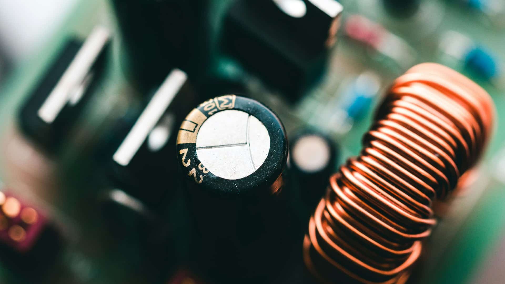
Acting like tiny batteries that store electrical energy in an electric field, capacitors are fundamental components in electronics. They’re incorporated into power supplies, timing circuits, and filters in audio equipment, among a broad range of other applications.
If you’re just starting out in electronics – perhaps playing around with a breadboard project, or studying physics at GCSE or A-level – you will often find that in order to achieve a certain desired capacitance value, it is necessary to combine multiple capacitors.
In such situations, you will greatly benefit from understanding what it means when capacitors are linked together in parallel and series configurations, as well as how to perform the associated calculations. So, in this article, we will take a closer look at these vital aspects.
Introducing Capacitance and Capacitors
For readers who may need gaps in their knowledge filled in, let’s go back to the very beginning:
- Capacitance is the ability of an electrical component, such as a capacitor, to store electric charge, measured as the ratio of the stored charge to the voltage across it (C = Q/V). It’s a measure of the amount of charge (Q) a device can hold for a given potential difference (voltage, or V).
- A capacitor is a passive electronic component that stores electrical energy in an electric field. In this sense, its behaviour has been likened to that of a tiny and fast-charging (or discharging) battery. It comprises two conductive plates separated by an insulator, the latter called a “dielectric”.
The Essentials of Capacitors in Parallel
Wherever you see a reference to capacitors being connected in parallel, this means they are wired side-by-side in the given circuit. This arrangement effectively increases the total plate area, which in turn, allows the circuit to store more charge.
In a parallel capacitor configuration, the total capacitance is the sum of all the circuit’s individual capacitances. This makes the combination act like one large capacitor.
The formula to remember for figuring out total capacitance across parallel capacitors, then, is: Ctotal = C1 + C2 + C3 + …. So, to give an example, if you were to connect a 10-microfarad (µF) capacitor and a 220µF capacitor in parallel, the total capacitance would be 230µF.
Capacitors are often linked together in parallel in power supplies to smooth out voltage ripples. They are also frequently used in situations where a large value (such as 2,000µF) is required, but only smaller-value capacitors are available.
The Essentials of Capacitors in Series
The connection of capacitors in a series arrangement involves them being placed “end-to-end” in a single path. This configuration causes the voltage to divide across the various capacitors in the chain. However, the charge on each capacitor remains the same.
Arranging capacitors in series causes the total capacitance to decrease. Indeed, in such a network of capacitors, the total capacitance is always less than the smallest individual capacitor in the chain.
| Feature | Parallel Capacitors | Series Capacitors |
|---|---|---|
| Total capacitance | Increases | Decreases |
| Formula | Ctotal = C1 + C2 + C3 | 1/Ctotal = 1/C1 + 1/C2 + 1/C3 |
| Voltage | Same voltage across each capacitor | Voltage divides across capacitors |
| Charge | Charge is distributed between capacitors | Same charge on each capacitor |
| Common use | Increasing total capacitance | Increasing voltage-handling capability |
To calculate total capacitance for a group of capacitors in series, you will need to use the reciprocal method. So, be sure to take a note of the formula: 1/Ctotal = 1/C1 + 1/C2 + 1/C3 + …. Again, to set out an example: if you have two 10µF capacitors in series, the relevant calculation would be 1/Ctotal = 1/10 + 1/10 = 0.2. Inverting this gives a total of 5µF.
A common motivation for engineers to opt for a series arrangement of capacitors, is so that the total voltage rating can be increased. While the total capacitance drops, the total voltage that such a combination of capacitors can handle is the sum of the individual ratings.
Remember That Online Calculators Are Available to Help!
You can, of course, perform the aforementioned calculations manually. However, to help verify the accuracy of any manual workings-out you do, in addition to boosting efficiency during your projects, it can be useful to have a good capacitor calculation tool bookmarked.
Getting to grips with parallel and series capacitor calculations will greatly help you realise the potential of your electronics projects.
Frequently Asked Questions About Capacitor Calculations
How do you calculate capacitors in parallel?
To calculate the total capacitance of capacitors connected in parallel, add the individual capacitance values together. The formula is Ctotal = C1 + C2 + C3. For example, a 10µF capacitor connected in parallel with a 220µF capacitor produces a total capacitance of 230µF.
How do you calculate capacitors in series?
For capacitors connected in series, add the reciprocal of each capacitance value. The formula is 1/Ctotal = 1/C1 + 1/C2 + 1/C3. The result is then inverted to find the total capacitance.
Does connecting capacitors in parallel increase capacitance?
Yes. Capacitors connected in parallel increase the total capacitance because the individual capacitance values are added together.
Does connecting capacitors in series reduce capacitance?
Yes. The total capacitance of capacitors connected in series is always lower than the smallest individual capacitor in the combination.
What is the formula for capacitors in parallel?
The formula for capacitors connected in parallel is Ctotal = C1 + C2 + C3. The total capacitance is the sum of all the individual capacitances.
What is the formula for capacitors in series?
The formula for capacitors connected in series is 1/Ctotal = 1/C1 + 1/C2 + 1/C3. After calculating the reciprocal sum, the result is inverted to obtain the total capacitance.
What happens to voltage when capacitors are connected in series?
When capacitors are connected in series, the applied voltage is divided across the individual capacitors. The voltage distribution depends on the capacitance values.
What happens to charge in capacitors connected in series?
In a series capacitor circuit, the charge on each capacitor is the same, although the voltage across each capacitor may differ.
Why are capacitors connected in parallel?
Capacitors are connected in parallel when a higher total capacitance is required. This arrangement is commonly used in power supplies to help smooth voltage ripple or when a large capacitance value is needed from smaller available capacitors.
Why are capacitors connected in series?
Capacitors can be connected in series to increase the overall voltage rating of the combination. However, the total capacitance decreases and must be calculated using the reciprocal formula.
What happens when two 10µF capacitors are connected in series?
Two identical 10µF capacitors connected in series produce a total capacitance of 5µF. The calculation is 1/Ctotal = 1/10 + 1/10, giving a reciprocal result of 0.2, which is then inverted to produce 5µF.
What happens when a 10µF capacitor and a 220µF capacitor are connected in parallel?
The total capacitance is 230µF because parallel capacitances are added together: 10µF + 220µF = 230µF.
What is capacitance?
Capacitance is the ability of a component to store electrical charge. It is measured in farads and is calculated using the relationship C = Q/V, where C is capacitance, Q is charge and V is voltage.
Are capacitor calculators useful?
Yes. An online capacitor calculator can help check manual calculations and save time when working with multiple capacitor values. However, understanding the underlying series and parallel formulas remains important for electronics and physics students.
Is this topic useful for GCSE and A-level Physics students?
Yes. Understanding capacitance, charge, voltage and capacitor combinations can be useful for students studying relevant electricity and electronics topics at GCSE and A-level, depending on the specific qualification and syllabus.
